

December 2010
 Hot glue and wire
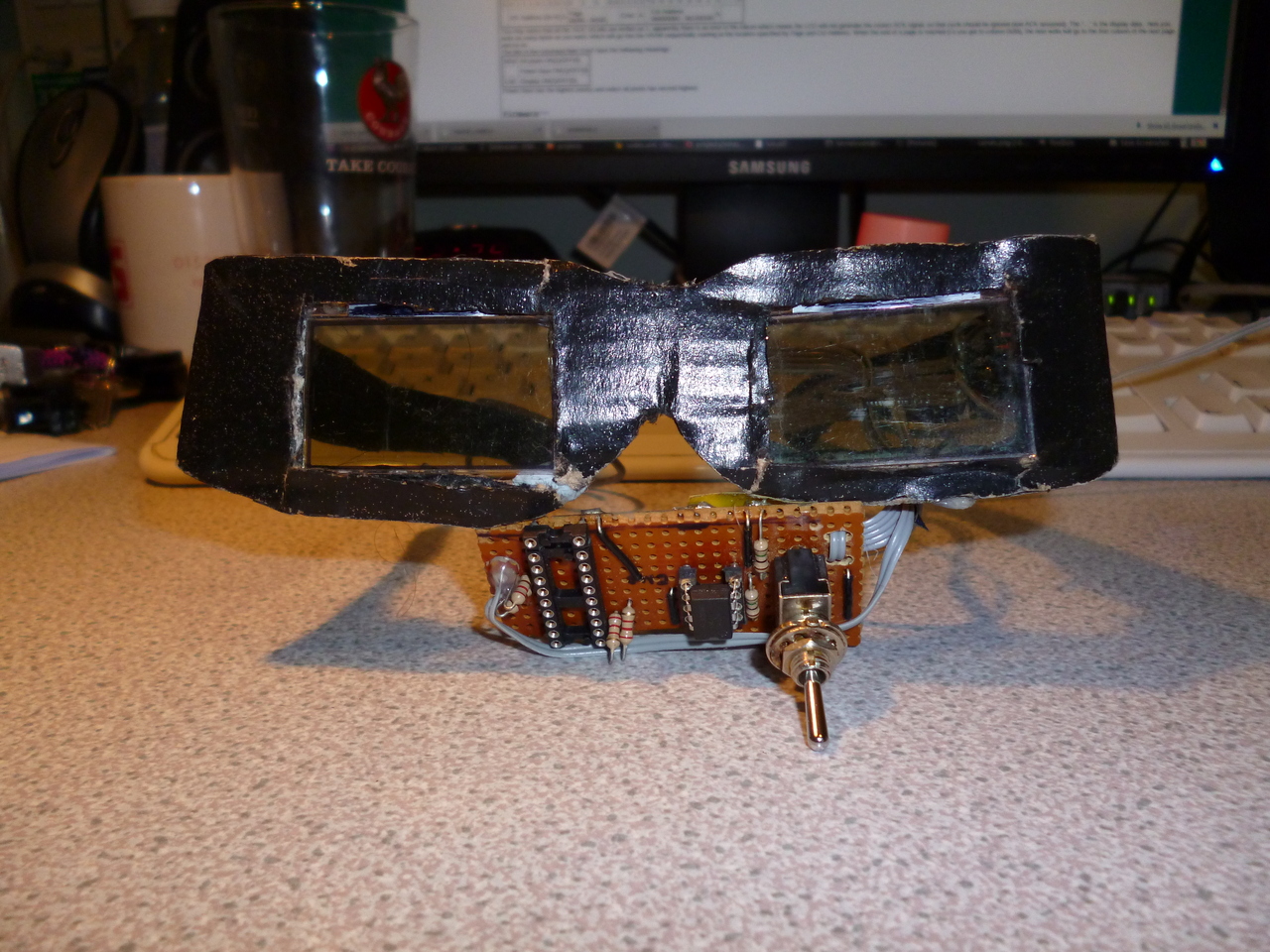 Stylish and robust
I built some glasses with LCDs as lenses for a Christmas fancy dress party, exhibiting craftsmanship that is... errr... second to none o.0
The project was hastily thrown together in the evenings of the week running up to the party, so if ever anything can be classed a 'quick and dirty' hack, this is it.
The LCDs came from scrapped phones, and are 101*40 pixel graphic displays, which are controlled over a (poorly implemented) i2c bus. The glasses run off a couple of old camera LiPo batteries and an Attiny2313.
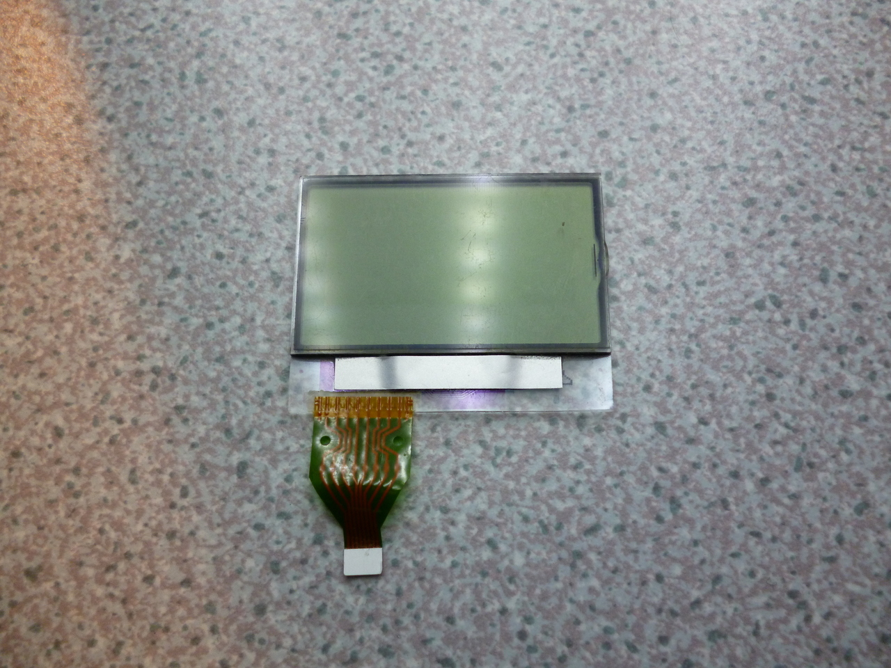 Front of Display
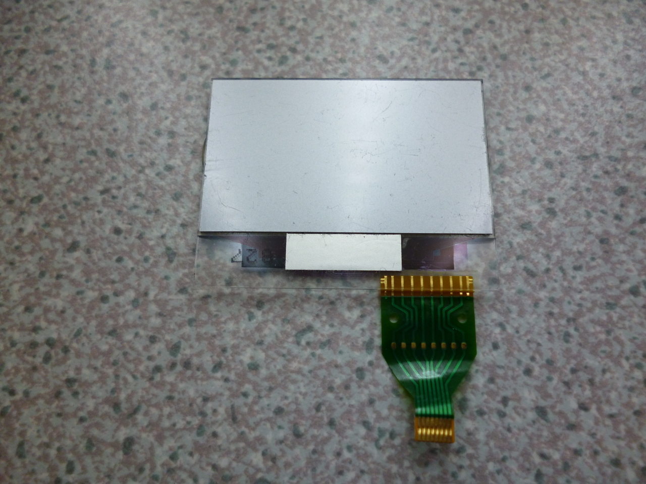 Rear of Display (Pin 1 on right)
The display used is an 8-pin affair, a Seiko S-4548ACG (I have recently written a linux kernel driver for this display. Find out about that here). This display doesn't exist anywhere on the internet (except in some obscure patent application), however I was fortunate enough to obtain a datasheet and get it working.
The display pinout is (pin1 is on the right when looking at the back of the display):
| Pin | Symbol | Function | Comment |
|---|---|---|---|
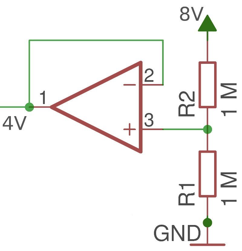
| 1 | VLCD | VLCD | VDD-8V - VDD-5V |
| 2 | VSS | Logic Ground | 0V |
| 3 | VDD | VDD | 2.4V - 5.5V |
| 4 | SCL | I2C Clock | ~100kHz (though I managed more) |
| 5 | SDA | I2C Data | Write address 0x74 |
| 6 | OSC1 | RC Oscillator input | Connect 470k across OSC2/OSC1 |
| 7 | OSC2 | RC Oscillator output | |
| 8 | VDD | VDD | Tie 3 & 8 together externally |
The display's VRAM is split up into 5 pages (rows) of 101 bytes, so that each bit in each byte represents a pixel.
The I2C transaction looks something like this:
| S | 0 | 1 | 1 | 1 | 0 | 1 | 0 | 0 | 1 | 0 | 1 | 1 | 0 | 0 | 1 | 1 | 1 | 1 | * | 0 | 0 | 0 | 0 | 0 | 0 | 1 | 1 | . | . | . | P |
| I2C Address (0x74) | A | Page 0b000 - 0b100 |
Cmd | A | Col Address 0b0000000 - 0b1100100 |
A | |||||||||||||||||||||||||
The bits in the command field 'Cmd' have the following meanings:
| MSB | All pixels ON(1)/OFF(0) |
| - | Power Save ON(1)/OFF(0) |
| LSB | Display ON(1)/OFF(0) |
Firmware(top)
 "Aha! That should be a '1'!"
 Let it snow!
As much as I would have loved to implement a lovely, neat, general-purpose, hardware-accelerated I2C stack... I didn't.
Let it snow!
As much as I would have loved to implement a lovely, neat, general-purpose, hardware-accelerated I2C stack... I didn't.
This being my first attempt at I2C on an AVR, I didn't have a ready-to-use I2C library (and though I did look online, I didn't like any of the implementations I saw). Given the tight time constraint, I wrote code to bit-bang the communications with the display.
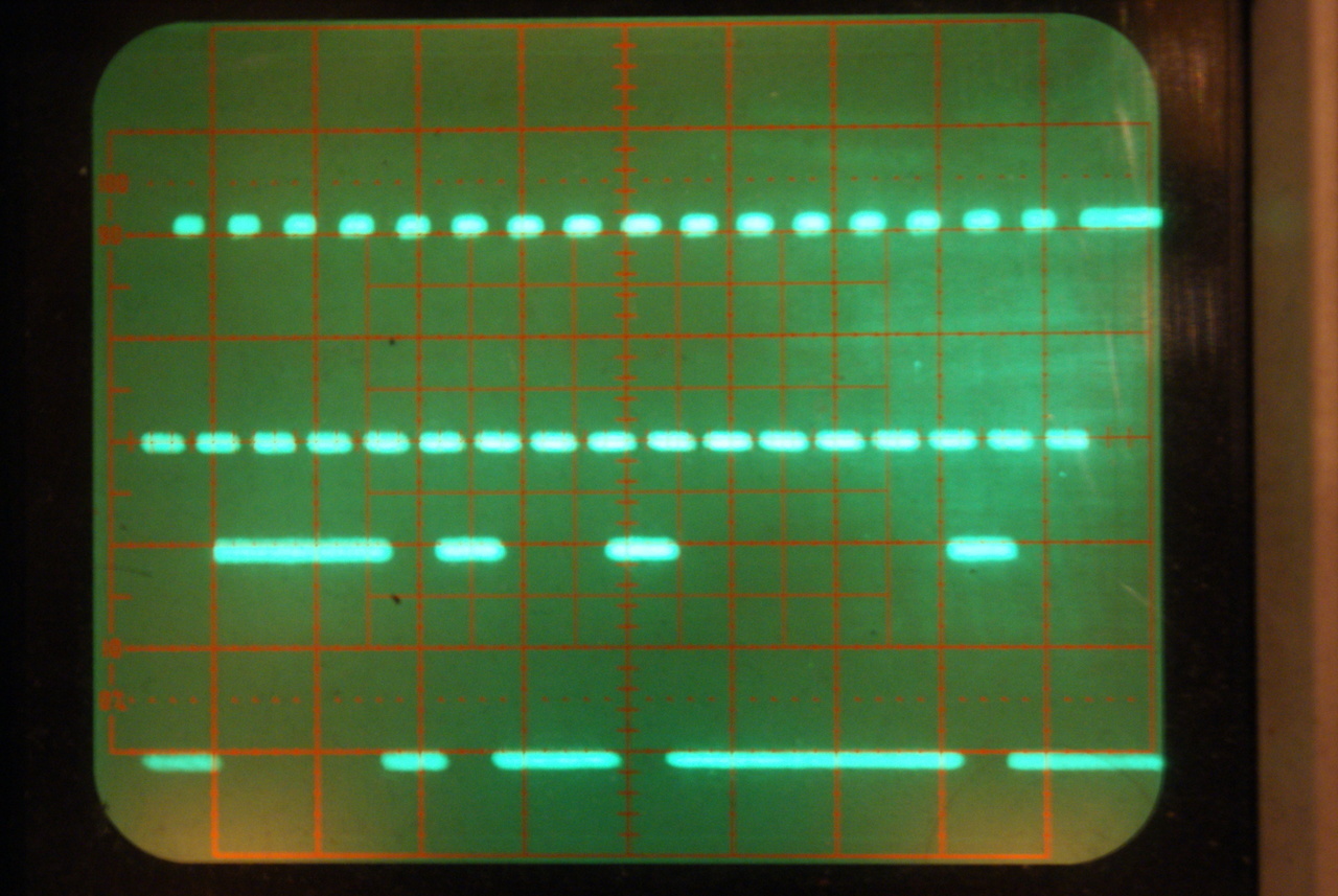
As the screens are write-only, I only bothered to implement writing, and was amazed when I managed to get the screen to do something (after tracking down the odd erroneous bit on my oscilloscope).
Once I could write to the screen, I had to decide what I was going to actually show on it. I broke out the GIMP and drew a little snowman, as well as 5 'pages' of snow (101*8 pixels), and used the ever helpful "C header file" output to save the monochrome bitmaps into something I could use. I had to do some trivial modification to get the images into the 1 bit per pixel format I needed, and then got to work getting them onto the actual screen.
By writing each 'page' of snow to each page of the screen, then incrementing the page number I started on, I could get a nice falling snow effect, and then I overlayed the snowman and sat back and admired my work.
"Aha! That should be a '1'!"Let it snow!This being my first attempt at I2C on an AVR, I didn't have a ready-to-use I2C library (and though I did look online, I didn't like any of the implementations I saw). Given the tight time constraint, I wrote code to bit-bang the communications with the display.
As the screens are write-only, I only bothered to implement writing, and was amazed when I managed to get the screen to do something (after tracking down the odd erroneous bit on my oscilloscope).
Once I could write to the screen, I had to decide what I was going to actually show on it. I broke out the GIMP and drew a little snowman, as well as 5 'pages' of snow (101*8 pixels), and used the ever helpful "C header file" output to save the monochrome bitmaps into something I could use. I had to do some trivial modification to get the images into the 1 bit per pixel format I needed, and then got to work getting them onto the actual screen.
By writing each 'page' of snow to each page of the screen, then incrementing the page number I started on, I could get a nice falling snow effect, and then I overlayed the snowman and sat back and admired my work.
So far so good... but it was still early, and encouraged by my success so far I wanted more. The first thing was to make the snowman move - simply shifting the starting
column and bouncing back upon reaching the edge. "Too easy!" I said, and set about finding something else. Linerider was a pretty popular game when
I was at school, and I thought having the little dude on his sleigh dart across the glasses every now and again would be pretty cool. After grabbing an image off Google,
making it monochrome and splitting it into pages like the others I added the image to the scene. The finished animation can be seen in the video. You will also notice the white light is fading in and out,
I added an LED to each eye and used a couple of the Attiny's PWM pins to make them fade in and out to provide some illumination for the screen. Of course the problem with that was
the LEDs completely whited out my vision whilst I was wearing the glasses, making it impossible to see anything unless the area was brightly lit.
Hardware(top)
 Power Supply
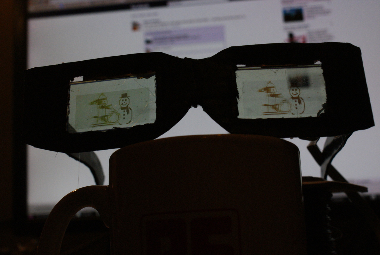 I should be a fashion designer
A few wires and a rubber band later, and my creation was finished.