

 The reset circuitry differences (from page 1)
One of the things that was missing from the Rev 1.0 Raspberry Pi was the ability to reset it. Once the OS was halted, the only way to reboot was to pull the power and plug it back in again. Of course this is the risk of being an early adopter... but we can fix it! The Rev 2.0 added a couple of pads to the PCB which when shorted together would cause the SoC to reset, thus resetting the Pi.
I have a Rev 1.0 Pi, and I need the reset functionality for a project I'm working on, so here's a little detail on how to add reset to the Rev 1.0 board. This does require sodlering onto the Pi's motherboard, but it's not too dicey, infact you don't even need a magnifier.
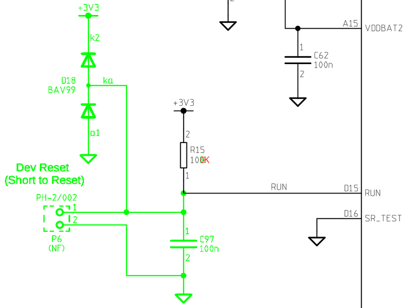
The changes to the Rev 2.0 board that add the reset switch are miniscule - a debounce capacitor was added, and a signal brought out to a pad alongside a ground. (Oh, and some protection circuitry, that I figured wasn't really necessary as long as you're careful). The image on the right highlights the schematic changes.
So now we know what the differences are, what do they mean?
- The two diodes, D18 (a BAV99)
- These are protection circuitry.
- The top one ensures that you can't overvolt the RUN pin, by clamping any positive voltage to ~(3.3 + 0.6) V
- The lower one protects from negative voltages, ensuring the RUN pin can't go below ~(0 - 0.6) V
- These can probably safely be excluded, as long as you're careful not to over/undervolt the RUN pin
- R15 from 10K to 100K
- In normal operation, the RUN pin needs to be pulled HIGH, this is the purpose of R18
- When you short the reset pads on a Rev 2.0 board, you pull the RUN pin directly to ground. R18 then determines the current travelling through that path
- The increase to 100K reduces the short-circuit current from 0.33 mA to 0.033 mA. In reality, it makes so little difference I wouldn't worry about it
- In combination with the capacitor C97, it also forms one half on an RC circuit, preventing the SoC from resetting multiple times due to contact bounce. A lower value means a lower time constant, but again, the real-world effect is probably negligible.
- C97, 100 nF capacitor
- This capacitor is to "debounce" the reset input. This means that when you short the pins on P6 (the reset pads), you get one nice clean transition from HIGH to LOW and back to HIGH again when you break the contact.
- This is a useful feature, and so you should include the component to ensure stable operation of your reset.
- P6, the reset connector
-
On Rev 2.0 boards, shorthing these two contacts results in a reset.
 My installed reset circuitry
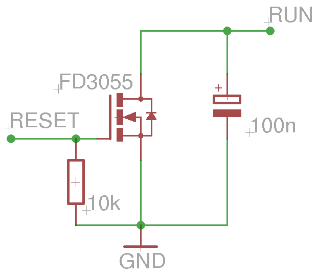 TTL level reset circuit
For my purposes, a single TTL level input to cause a reset was more useful, so I also added a FET to effectively short P6 in response to a high input. The schematic for my reset circuitry is shown in the image on the right. If you just want to replicate the behaviour of the Rev 2.0 board, don't bother with the FET and just add the capacitor.
To actually add the circuit to the Pi, I built the circtuit on stripboard and stuck it down next with a sticky pad in the gap next to S2. Note the wire going to R15, its position is important, being attached to the side of the resistor closest to the SoC. You must solder this wire to the correct side of the resistor, or you will be directly shorting the power supply.
You'll also need to find a GND connection for your reset circuit, I took it from Pin 1 (the leftmost one) of the 1.8 V regulator RG1. This is nice and big making for easy soldering. Then you just have to break out your new RESET input to something convenient. I used a single pin header, applying 5 V here (e.g. from the output of a microcontroller...) resets my Pi.