

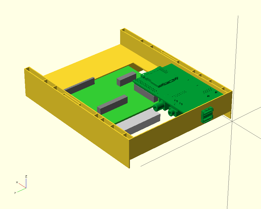
 OpenSCAD Mock-up
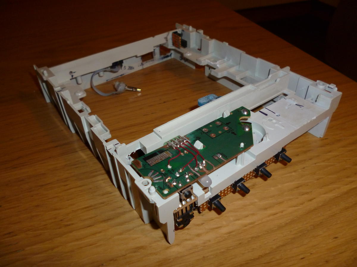 Chassis bottom (the sockets are glued in)
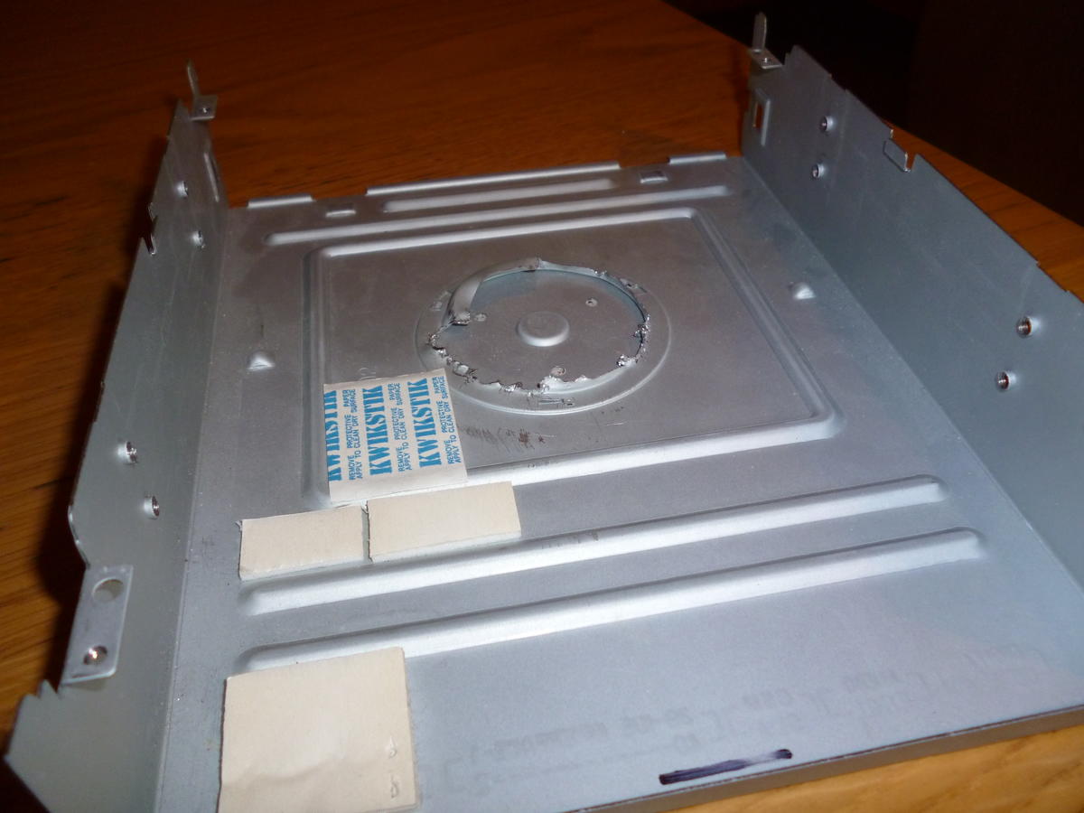 Nibbled stabiliser mount
The case is (obviously) a standard 5.25" optical drive. A TS-H552 according to the sticker on the top. I pulled out the drive tray and made fairly extensive modifications to the plastic chassis. If I ever did this again, I would start from scratch and build a chassis to fit the shell, as cutting up the innards was hard, long and tedious work. I removed the drive-opening motor, but kept the board as it had the eject button mounted on it (for use as a a power button).
The only external modifications are at the rear, to let the USB and ethernet ports out, as well as an audio output and power in. The USB for the HDD just snakes out through a gap where the PCB used to be to plug in to one of the ports. I didn't really want to hack straight onto the R-Pi's motherboard (they were still very hard to get hold of when I was doing this!), and it works fine as-is.
The metal exterior is completely unchanged, but I did have to pull off some of the stabilising disc holder on the inside as it was in the way of the Pi. It's a real mess - I didn't have the right tools, so I used pliers and metal fatigue! But, it's on the inside, so who cares?!
 The power line
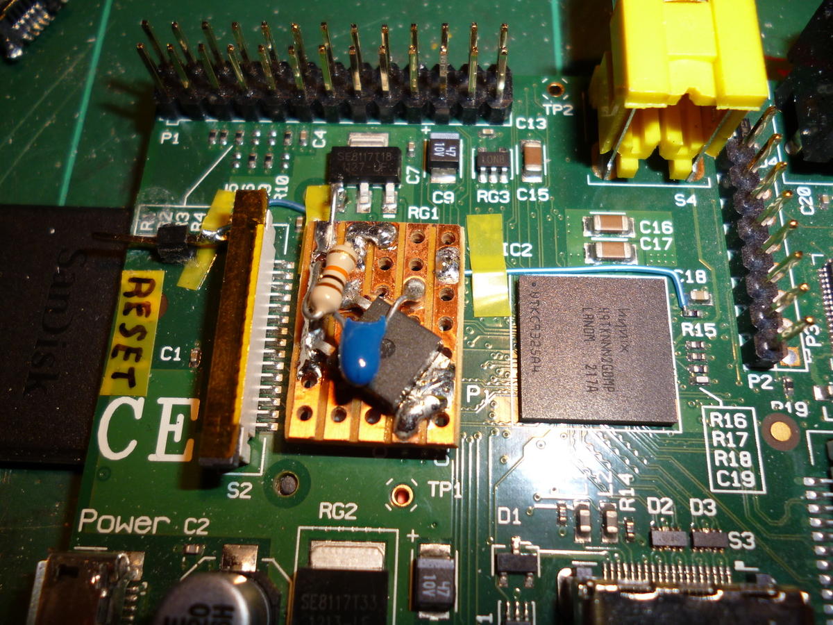 Reset circuit
My goal was always to keep the Raspberry-Pi unmodified for this project. I almost succeeded - however the Rev 1.0 Pi cannot be reset electronically (so you can't bring it back from HALT). I added some reset circuitry - you can read the details here, so that the Atmega can reset the Pi to turn the system on.
The only other modification is a wire from the GPIO header to the power input. The reason for this is all the power for the Pi is fed into the 5V pin on the GPIO header. There was some doubt on the 'net whether the traces on the board were beefy enough for this job, so I added another wire in parallel just to make sure. It's probably unneccesary.
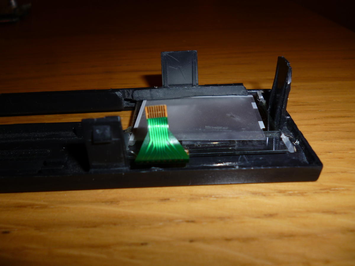 LCD mounted in the front panel
 The LCD breakout board
 The LCD breakout board
At the front, where the drive tray would be I had to cut away some plastic to let the LCD sit flush with the inside of the slot. This was probably the most difficult part of the whole thing.
The LCD itself is a S4548, which I have used a few times before. Details for it can be found on the LCD Shades and s4548 pages. It requires a negative voltage rail, which is generated by the Atmega via a couple of diodes and a capacitor.
The LCD has a 0.5 mm pitch FPC, which I have previously soldered to, but this time I wanted to do it right. As such, I etched my very first PCB to make a little breakout board. I think it was an ambitious first-etch, but it came out fine the first time! Oh, except for I had it mirrored; so it came out perfect the second time ;-) This just gives me a nice easy 0.1" header to connect to, and holds a 470k resistor for the LCD's on-chip oscillator.
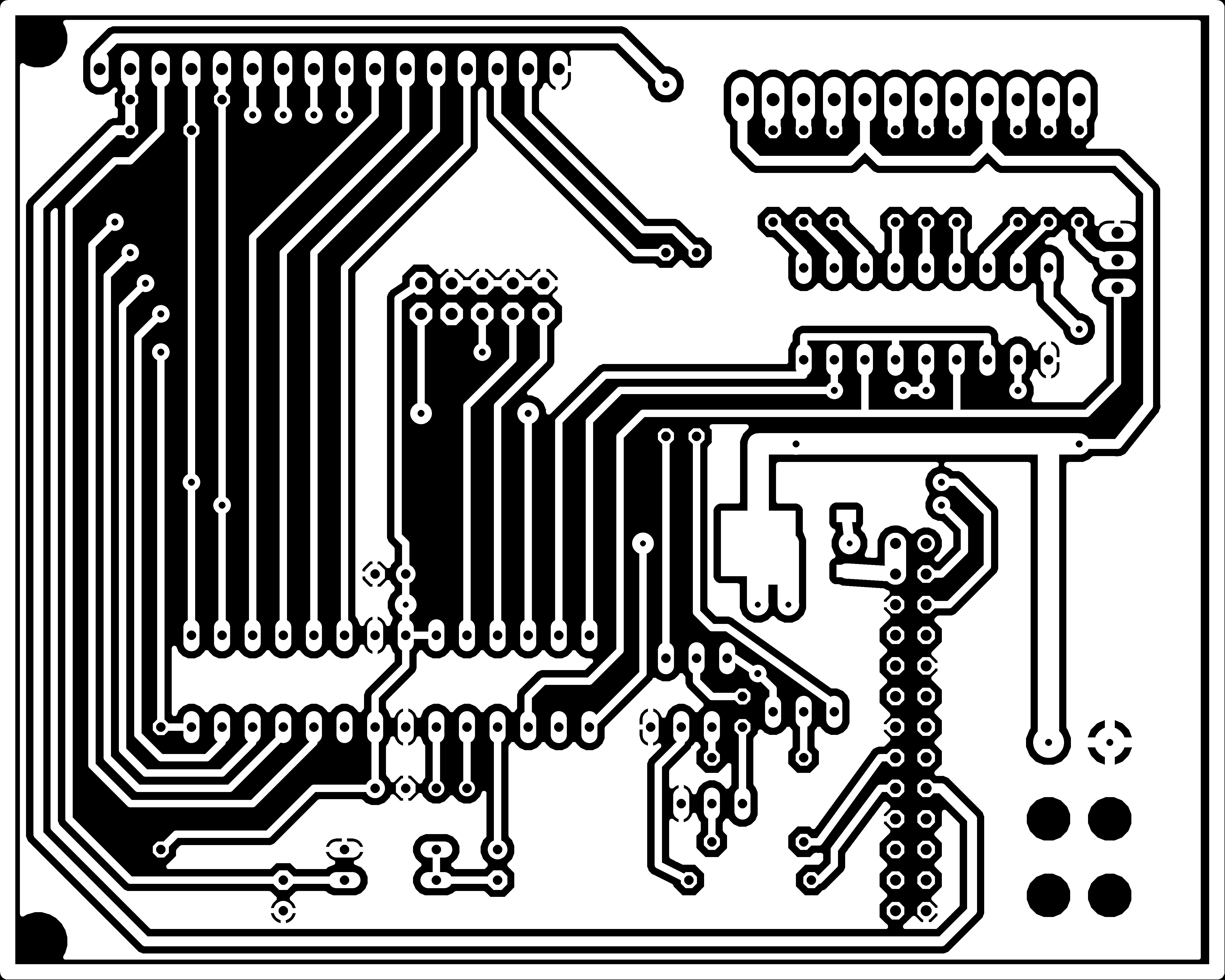 The board design
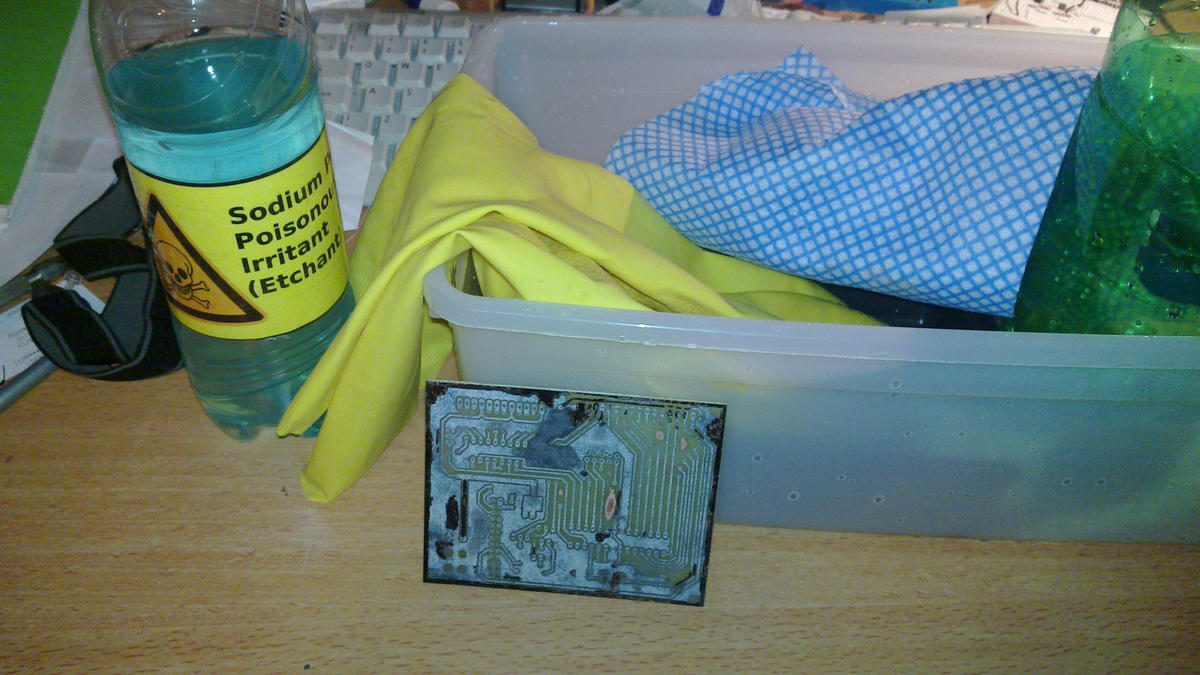 The board after etching
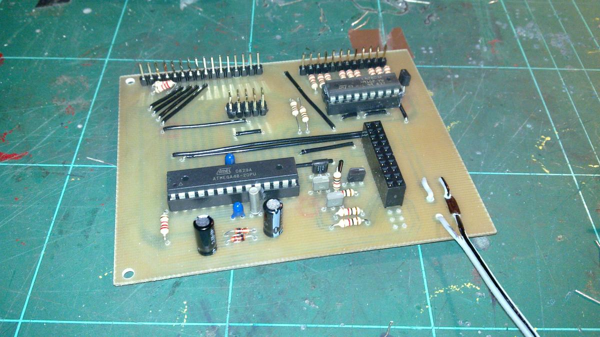 The populated board
The front-panel has a collection of pushbuttons and a scroll-wheel for user input. I didn't think interfacing these directly with the Pi was a good idea, for 1) because linux isn't real-time, and 2) I wanted to be able to handle the power button with the Pi turned off.
Instead, I designed and etched a board which houses an AVR Atmega 168, the components for the LCD's voltage inverter, and some transistor LED drivers. This was my second etch, and again it came out pretty well. It connects directly on to the Raspberry Pi's expansion header, communicating via i2c, and also connects to the reset input I added to the Pi.
This board also takes the power input from the rear of the case, and feeds it to the Pi and the USB to SATA converter. One final point to note is that the AVR has a 32 kHz watch crystal attached, as I was hoping I could use it as an RTC - but I haven't got round to writing that bit of the firmware yet.
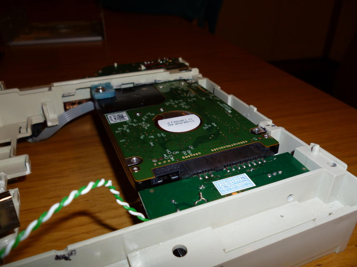 The hard-drive mounted in the case
The final component is the HDD and USB to SATA converter. The hard-drive bolt-hole spacing fits conveniently with some channels in the case, so it is bolted to those, with the USB to SATA converter sitting at the rear of the case, with a hole drilled for its LED.
I feed power directly to the USB to SATA converter from the Pidrio board, and have a short USB cable with just the data lines to connect to the Pi.
 All the components mounted (top side)
 All the components mounted (bottom side)
 View from the rear
 Annotated components